The energy consumption of a device is especially important when those devices are Internet of Things (IoT) devices. This fact applies to devices running ESP32 hardware as well.
However, you cannot just simply measure the current of an ESP32 device by connecting it to an oscilloscope or anmeter of your choice. If you are not careful, you may even risk damaging the device.
To the best of my knowledge, there are not many resources that explain how to properly measure the current of ESP32 microcontrollers.
In this guide, I would like to share what I learned in the process of measuring the energy usage of my own ESP32 devices and common pitfalls to avoid.
In this tutorial, I will specifically be using an ESP32-H2 devkit. Although I never measured the current of other devices beyond the ESP32-H2, I believe the steps in this tutorial should still apply to other ESP32 devkits that contain a J5 Header (such as an ESP32-C6).
Choosing the Right Measurement Tool
You can measure the current of an ESP32 device using an oscilloscope. However, doing so is challenging, since oscilloscopes measure voltage, not current. To do so, you will need to indirectly measure the current by measuring the voltage drop of the device. Even then, you may not even get fully accurate measurements when your ESP32 device is operating at really low currents, such as during deep sleep, due to noise.
Oscilloscope are not designed for this task. They are really good at measuring voltage at really low timescales (e.g. in the range of micro- or nanoseconds), but they are not good at measuring voltage when the voltages are really small (e.g. in the range of microvolts). As a result, obtaining the current through the voltage drop measured by an oscilloscope will not get us far.
To measure currents, especially really low currents, we will need to look for other tools. To find these tools, we need not look further than the ESP-IDF Programming Guide:
Therefore, an ammeter suitable for measuring current in Deep-sleep mode should have low internal resistance and, ideally, switch current ranges dynamically. We recommend two options: the Joulescope ammeter and the Power Profiler Kit II from Nordic.
In this tutorial, I will be using the Nordic Power Profiler Kit II (PPK2).
As an example of the limitations of oscilloscopes when measuring really low currents, shown above are waveforms displayed when measuring the deep sleep current of an ESP32-H2 using the Digilent Analog Discovery 3 (AD3) oscilloscope, with the AD3 Current & Power Adapter extension. The expected deep sleep current of the ESP32 should be ~7 uA, but the AD3, with the Current & Power Adapter, can only measure at around ~350 uA granularity.
More accurate waveforms are obtained when measuring the deep sleep current 1 of an ESP32-H2 using the PPK2.
How to Not Measure Low Currents
You can set up an ESP32-H2 with the PPK2 by using jumper wires to connect:
- the
VOUTport of the PPK2 to the5V02 pin of the ESP32 device, and - the
GNDport of the PPK2 to theGNDpin on the ESP32.
In this configuration, you can use the PPK2 to measure the current of the ESP32-H2 while the PPK2 itself is providing 5V of power. This is how I initially approached the measurement of my ESP32-H2 device.
However, this approach will not work when the ESP32-H2 is consuming really low currents in the uA range: the PPK2 will report much higher currents than expected.
When measuring the deep sleep current of my ESP32-H2 when it ran the ESP32 OpenThread boilerplate deep sleep SED program, the PPK2 reported a current of ~1.21 mA, when it should have instead measured the current at ~7 uA, the expected value of the deep sleep current for an ESP32-H2 3.
When the ESP32-H2 runs the ESP32 OpenThread boilerplate deep sleep SED program and has its 5V0 pin connected to the VOUT port of the PPK2, the current measured by the PPK2 is around ~1.21 mA, rather than ~7 uA.
The J5 Header
These inaccurate low current measurements occur when the J5 header jumper of the ESP32-H2 has not been removed.
The J5 header of the ESP32-H2. The power-on LED is off when the J5 header jumper is removed, even though the ESP32-H2 module itself was having its power supplied by USB.
In the picture above shown in the right, I showed my ESP32-H2 with the J5 jumper removed while its UART port was connected to USB. DO NOT DO THIS!4 Removing the J5 jumper from an ESP32-H2 while it is being supplied with 5V of power could damage the device. This applies to USB serial and UART connections as well, as USB connections supply 5V of power. You will need to supply the ESP32-H2 with 3.3V of power when the J5 jumper is removed. Even though I did not measure the current of other ESP32 devices, I believe this warning will still apply to any ESP32 devkits that contain a J5 header (such as the ESP32-C6).
In order to accurately measure the current of an ESP32-H2, the J5 jumper will need to be removed 5 from the ESP32-H2 for the duration in which the PPK2 is measuring the current of the device.
Measuring Small Currents Correctly
To properly measure low currents using the PPK2, we will need the following setup:
-
Connect the
VOUTport of the PPK2 to the3V36 pin of the ESP32-H2, or to one of the two J5 pins that are visible when the J5 jumper has been removed. -
Connect the
GNDport of the PPK2 to theGNDpin of the ESP32-H2.
Set the PPK2 to provide 3.3V of power to the ESP32-H2. Do not set the PPK2 to provide 5V of power, as doing so can damage the device. After following these steps, the PPK2 will be able to accurately measure low currents.
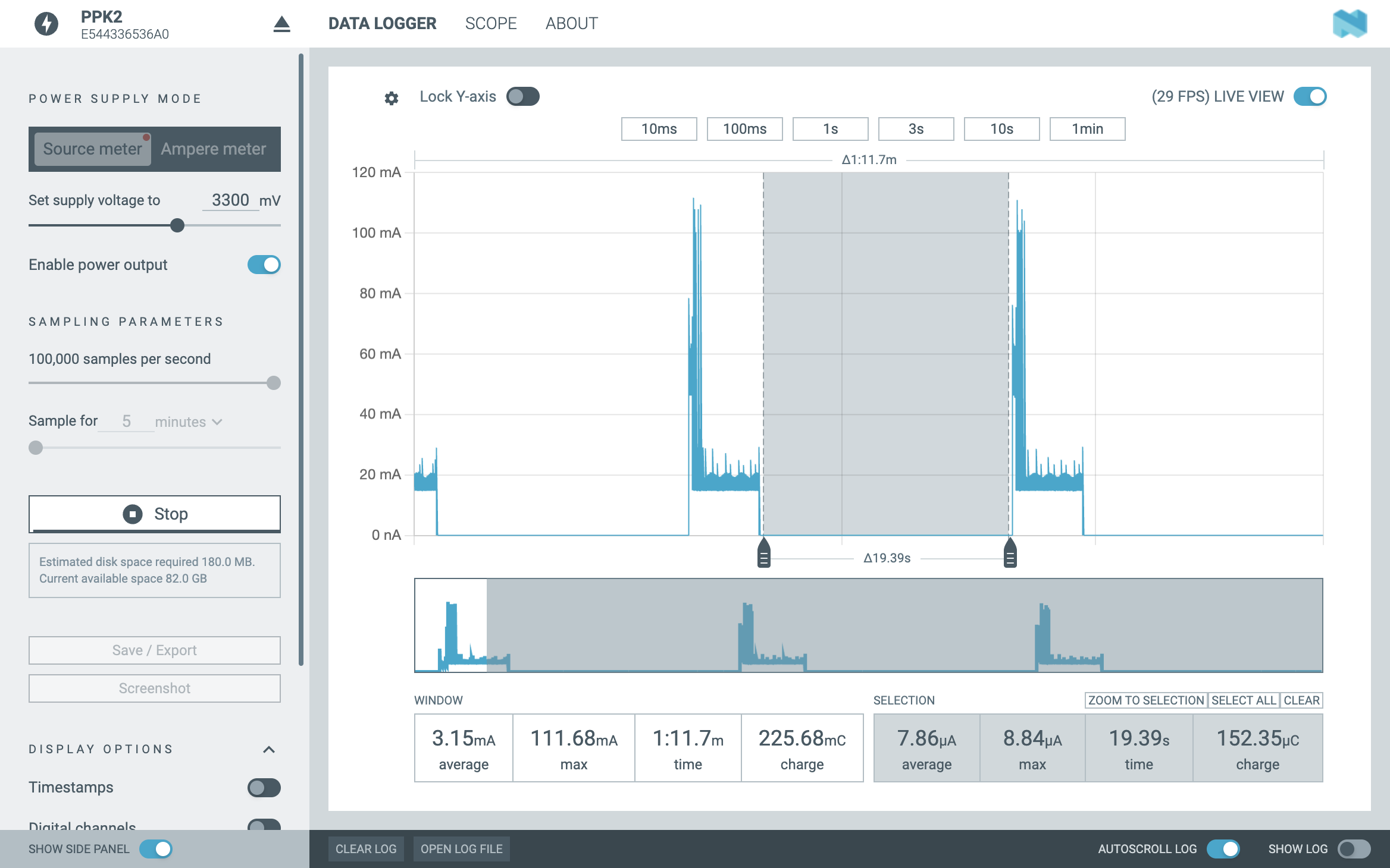
The PPK2 measured the deep sleep current of my ESP32-H2 at around ~7.8-8.84 uA after the J5 header was removed. Such measurements are much closer to the expected deep sleep current of 7 uA as stated in the ESP32-H2 datasheet.
Helpful Resources
In this section, I compile the helpful resources that I used when I was in the process of figuring out how to properly measure the low currents of my ESP32-H2s during deep sleep with the PPK2.
-
The ESP32-H2 Devkit Documentation, particularly the section about the J5 header.
-
The conversation I had with Espressif engineer
Spritein the ESP32 forums about the purpose of the J5 header. I want to thankSpritefor taking the time to teach me about the J5 header. -
The Current Consumption Measurement of Modules page in the ESP-IDF Programming Guide. This webpage describes the tools recommended by Espressif to measure the current of ESP32 devices, along with discussing the general approach to measuring the current of such devices.
-
The conversation I had in the Digilent forums when I was figuring out how I could accurately measure the deep sleep current of an ESP32-H2 using the Analog Discovery 3. I would like to thank Digilent engineers
JColvinandattilafor teaching me how to use the AD3 with the Current & Power Adapter to measure the current of my ESP32-H2 devkit. -
The PPK2 video review by Circuit Digest on YouTube. The video review contained a short tutorial on how to set up the PPK2 with an ESP32 device. Although the ESP32 device used in the video was different than the ESP32-H2, I found the video helpful nonetheless when initially measuring my ESP32-H2 with the PPK2 with 5V of power (before I learned about the J5 header).
Footnotes
-
In the screenshot, the deep sleep current was measured at ~11-12 uA, rather than 7 uA, which should be expected according to the Table 5-9 of the ESP32-H2 datasheet. The current measurement was higher than expected as I was using the PPK2 to measure a circuit which included the ESP32-H2, rather than measuring the ESP32-H2 directly, as I discuss later in the blog post. ↩
-
According to the ESP32-H2 GPIO pin layout diagram, the
5V0GPIO pin is used to provide 5V of power to the ESP32-H2. Since the5V0pin also appears in the ESP32-C6, I use the notation5V0to generally refer to the GPIO pin that allows an ESP32 device to be supplied with 5V of power. ↩ -
Table 5-9 of the ESP32-H2 datasheet states that the expected deep sleep current for the device is 7 uA. Furthermore, the screenshot shown in the
READMEfor the ESP32 OpenThread boilerplate deep sleep SED program shows that when the Joulescope energy analyzer was used to measure the deep sleep current of an ESP32 802.15.4 device running the program, it reported currents in ~7-8 uA range. ↩ -
I learned about the purpose of the J5 header from the ESP32-H2 Devkit documentation, and in the converstion I had with Espressif engineer
Spriteon the ESP32 forums. ↩ -
At the time I took the picture, I did not know that powering my ESP32-H2 with 5V while the J5 header was removed would cause any issue. It was not until I talked to Espressif engineer
Spriteon the ESP32 forums that doing so could damage my ESP32-H2 device. ↩ -
According to the ESP32-H2 GPIO pin layout diagram, the
3V3GPIO pin is used to provide 3.3V of power to the ESP32-H2. Since the3V3pin also appears in the ESP32-C6, I use the notation3V3to generally refer to the GPIO pin that allows an ESP32 device to be supplied with 3.3 of power. ↩